
1)- Introduction and principle of the radio link .
2)- The software in assembler for TI89, TI92 et TI92+ and SCREENSHOTs' TI92 !
3)- The diagram of the interface and datasheet of TCM3105pdf.
4)- The layers in PCB Boardmaker & GIF formats.
5)- The realization of the circuit (guide for the construction with pictures).
1)- Introduction and principle of radio link.
The data transmission is done at a low rate in order to use low-cost modulators and demodulators. The reason why the direct transmission with the TI92 is impossible is that the "normal" speed is too higher (30Kbps) and the 2 wires of the I/O port are used simultaneously in bidirectional mode. The software Dualnet under Fargo II (or normal operation mode for the TI89 and TI92+) allows to use a conventional asynchronous serial link at ARROUND 87bps in full-duplex mode (asynchronous type, 87bps, 8bits of data, 1 start bit, 1 stop bit, parity=none). It's allowed to use CASIO or HP48 pocket calculators with a speed of 1200bps (no parity) and without special software...We are in the ideal case to use any radio ham modem (like RTTY or Baycom).
The new TCM3105 based interface makes the assembling easier to do and efficencier to use.Concerning the TI92, the transmission rate was divided by 2 in order to minimize the out of synch effects provoked by the batteries' strengh. Some good batteries or recharged allows a messages' transfer without problems contrary to the software used in the TI92 radio network.Principle of data transmission of the calculator :
Principle of data reception of the calculator :
These 2 diagrams will be usefull during the assembly of the different boards...
2)- The software for TI92 (tested with Fargo II version 0.2.7.1) and the software for the TI92+ and TI89.
The main role of the software is to provide a constant transmission's rate under a specific transmission protocole for the TIs only. The chosen solution is the software emulation of an UART (Universal Asynchronous Receiver Transceiver) commonly used in the Personnal Computers and modems in hardware version (8250-16550 chips). The assembler software can create the electrical squares (bits) under the wished protocol and can receive them. Because of the high numbers of errors met during the perfecting phase, the softwares provided are in their experimental version (beta version if you like). The sources are provided too and they are commented in english and in french.
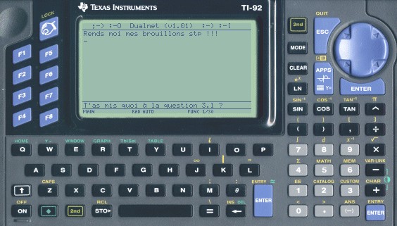
As you can see on the new following screenshot, each user has at one's disposal a screen of 12 lines, 40 characters by line. The screenshot shows you a dialogue between 2 users who are 20 meters apart with 3 walls between...and this without transmission problem as long as the batteries' strengh is good ! The radio link can be used too with 2 CASIO or HP48Gx pocket calculators without software, in fact the radio link simulates a crossed cable (RS232) with a max speed of 1200bps and no parity.
Click the following picture to see full-screen use of DualNet for TI92+:
Click to download Dualnet.zip (include: Dualnet.92p/9xz/89z the last version for TI92, TI92+ and TI89)
ps : special Thanks to Ticalc.org to provide in its files' archive some programs' sources under Fargo II very well commentated :-)).
3)-The interface's diagram for all systems (calculators, Windows95 with null-modem software, networked games...).
Schematic of radio modem at 1200bps (FM transmiter,FM receiver, modulator FSK/demodulator FSK adapted for TI92 calculators).
Click the following picture to see full-screen schematic:
The average price of the circuit in Europa (France) :
Part Price in FF (French Francs) / € (Euro)
FSK 1200bps modem U1 TCM3105 75FF-90FF / 11.43€-13.72€ X1 crystal 4.43361MHz 6FF / 0.91€ D1 1N4148 0.40 FF / 0.06€ T1 CBC857B(SMD) 1 FF / 0.15€ LED (green miniature model) 1 FF / 0.15€ SMD Capacitors recovery ! (arround 2.30FF / 0.35€) SMD Resistors 5FF / 0.76€ FM transmitter 88-108MHz T1 2N2222(classic package) 2.20FF / 0.34€ Z1 Zener diode 4.7v 0.80FF / 0.12€ SMD Resistors 2.50 FF / 0.38€ SMD Capacitors recovery (arround 8FF / 1.22€) RV1 multi-turns pot 5 FF / 0.76€ DV Varicap diode (BB106-BB106-BB112) recovery ! (arround 6FF / 0.91€ L1 6 turns, wire diam=0.5mm recovery ! FM receiver 88-108MHz U1 TDA7010T 30FF / 4.57€ SMD Resistors 2FF / 0.3€ SMD Capacitors recovery. (arround 15FF / 2.29€) L1 recovery.
--------------------------------------------- TOTAL (for 1 calculator) 162.2FF / 24.73€
The classic components like TDA7010T, crystal, transistor, diodes, résistors and chimical capacitors are easily available. On the other hand, as an indication, the TCM3105 was available in 1998 at Eurocomposant and at Electronique 33 Bordeaux (Electronic diffusion - Bordeaux France) Phone:05 56 52 14 18 . The SMD resistors are available too but the SMD capacitors can't be found easily. So the recovery of old electronic cards is a good solution but you will need a capacimeter (multimeter with Farad measurement).
The important quantity of received mails concerning the availabiliy and the price of the TCM3105 supposes that this chip is becoming obselete. Otherwise, this component can be found on old modem cards for PC like french cards which emulate the Minitel (Minitel is a french terminal for all the french houseolds). Actually, there is not pin to pin equivalence for the TCM3105. The best chip which could approaches the TCM3105 is the FX614 (modem compatible BELL 202) built by Consumer Microcircuits Limited (CML) but the Tx and Rx speeds are asymétrical and slower than the TCM3105... A good idea is to look on the website of Maxim (where some chip samples are free "orderable"), Philips and SGS-Thomson made FSK modems too.... A good alternative way is to build the modem around a PIC microcontroler (UART+ modulation(simple DCA & démodulation(DAC 1 bit like Hamcom interfaces)). So, the 9600kps modem proposed by the german group Baycom could be interresting to know how does it works. We can found on their website the plans of PIC based 9600kps modem but the source code is to sell !
If somebody have some data about PIC based modems, don't hesitate to send me a little mail at yb_net@yahoo.fr. Thx.
4)-The layouts in PCB Boardmaker & GIF formats.
PCB of radio modem at 1200bps (FM transmiter,FM receiver, modem FSK).
The realization can be made in 2 ways : a classic realisation with classic packages or a realization with SMD parts in order to reduce the size of the 3 circuits (transceiver + power supply stablization, receiver, FSK modem with the TCM3105 in classic DIL16 package but its pins were been curved (folded up).
PCB (double side) of FSK MODEM (component view):

PCB (double side) of FSK MODEM (track view=ground plane):
Location diagram :
PCB of FM TRANSMITTER: Location diagram :

PCB of FM RECEIVER:
Location diagram :
5)-The realization of the circuits (Construction tips and pictures).
Pictures of the different assemblied cards : these pictures were be shot with the frame grabber whose the diagrams are provided here !
Pictures of the TCM3105 based modem :
Notice that all the TCM3105's pins are curved. Don't forget to solder first the vias between the ground tracks and the ground plane...
Pictures of the TDA7010T based FM receiver :
Pictures of the FM transceiver and the power supply stabilization :
Construction tips : the how-to software and hardware :
The first step consists in checking the good working of the software part TI92-TI92 with the help of a crossed cable (CASIO like or a TI92/89 cable were the 2 data wires are crossed). The working is immediate and the TI92 doesn't break off during the messages' transmission. A bad working at this stage is due to the batteries' strengh of one of the TI (or the both), the batteries' voltage has to be higher than 4.9v...
If the first step is working good, then build 2 TCM3105 modems. The voltage on the pins 7 and 10 hasn't to be adjusted. Next, connect the 2 modem cards in crossing the 2 analogue input/ouput wires. Test the link with the software Dualnet.92p (or 89z,92z), it must have none difference with the previous step. If it's the CASIO or the HP48 version which interest you, remove the diode D1 and it works fine at 1200bps (no parity) but the voltages have to be well adjusted (pin7=2.7v and pin10=3.3v).
The third step is to realize the 2 FM transceivers (FM is more efficient against the parasites) which transmit on a free frequency. Check the good working of your FM transceiver with the help of a commercial receiver : you should heard the frequency of 1200Hz or of 2200Hz depending of the logical state of the input pin. If the signal is well heard (you have to adjust the C2 capacitor and the L1 self or in the worst of case the 2 resistors R1/R2 but it's not advised) go to the next stage.
The last step is the making of the 2 FM receivers which provide BF output signal (1200Hz/2200Hz). When you adjust the frequencies, use 2 free frequencies in order to avoid the over-modulation.
Your circuit is ready to work fine ! You can mount it in a shoes'box or...
Suggestion of accompaniment: place the boads inside the TI92 but it's 100% illegal and few efficient cause to the buses' parasites of the calculator.
Click the following picture to see full-screen diagram (or shift+left clic if your browser can't display it):
The author of the present circuit is not responsible for the troubles you will do at your calculator and for the use that you will have with it, this circuit is presented only in the experimental and educational limits. Furthermore the broadcasting of signals on the FM band (88MHz-108MHz) is prohibed by the law of your country. The open of your TI's calculator cancels the Texas Instrument guarantee and finally the circuit consumes arround 60 milliamperes so a premature wear of the batteries...it's really a circuit which is not a all good... ;-)
©YB 2000.
Maintained by Yannick.
This page contents Open Source Code and schematics for TI92 Radio Network. You can Use, Copy, Diffuse and Change this Software. You CAN'T copy this page and publish it on your website without mentionning the origin of it.
Last Updated .
This page URL is HTTP://www.ybnet.fr.st/singleti92_uk.html